Table of Contents [hide]
Patient Health Monitoring System using ESP8266 & Arduino:
With tons of new healthcare technology start-ups, IoT is rapidly revolutionizing the healthcare industry. In this project, we have designed the IoT Based Patient Health Monitoring System using ESP8266 & Arduino. The IoT platform used in this project is ThingSpeak. ThingSpeak is an open-source Internet of Things (IoT) application and API to store and retrieve data from things using the HTTP protocol over the Internet or via a Local Area Network. This IoT device could read the pulse rate and measure the surrounding temperature. It continuously monitors the pulse rate and surrounding temperature and updates them to an IoT platform.
The Arduino Sketch running over the device implements the various functionalities of the project like reading sensor data, converting them into strings, passing them to the IoT platform, and displaying measured pulse rate and temperature on character LCD.
You can check our previous projects related to Pulse Sensor if you are a beginner:
1. Heartbeat/Pulse/BPM Rate Monitor using Arduino & Pulse Sensor.
2. Pulse Rate Monitoring over Internet using ThingSpeak & ESP8266.
3. ECG Display using Pulse Sensor with OLED & Arduino.
Block Diagram:
This is a simple block diagram that explains the IoT Based Patient Health Monitoring System using ESP8266 & Arduino. Pulse Sensor and LM35 Temperature Sensors measure BPM & Environmental Temperature respectively. The Arduino processes the code and displays it to 16*2 LCD Display. ESP8266 Wi-Fi module connects to Wi-Fi and sends the data to IoT device server. The IoT server used here is Thingspeak. Finally, the data can be monitored from any part of the world by logging into the Thingspeak channel.
Bill of Materials:
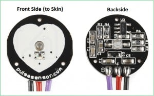
Pulse Sensor:
The Pulse Sensor is a plug-and-play heart-rate sensor for Arduino. It can be used by students, artists, athletes, makers, and game & mobile developers who want to easily incorporate live heart-rate data into their projects. The essence is an integrated optical amplifying circuit and noise eliminating circuit sensor. Clip the Pulse Sensor to your earlobe or fingertip and plug it into your Arduino, you can ready to read heart rate. Also, it has an Arduino demo code that makes it easy to use.
The pulse sensor has three pins: VCC, GND & Analog Pin.
There is also a LED in the center of this sensor module which helps in detecting the heartbeat. Below the LED, there is a noise elimination circuitry that is supposed to keep away the noise from affecting the readings.
LM35 Temperature Sensor:
The LM35 series are precision integrated-circuit temperature devices with an output voltage linearly-proportional to the Centigrade temperature. The LM35 device has an advantage over linear temperature sensors calibrated in Kelvin, as the user is not required to subtract a large constant voltage from the output to obtain convenient Centigrade scaling. The LM35 device does not require any external calibration or trimming to provide typical accuracies of ±¼°C at room temperature and ±¾°C over a full −55°C to 150°C temperature range.
ESP8266:
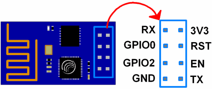
The ESP8266 is a very user-friendly and low-cost device to provide internet connectivity to your projects. The module can work both as an Access point (can create hotspot) and as a station (can connect to Wi-Fi), hence it can easily fetch data and upload it to the internet making the Internet of Things as easy as possible. It can also fetch data from the internet using API’s hence your project could access any information that is available on the internet, thus making it smarter. Another exciting feature of this module is that it can be programmed using the Arduino IDE which makes it a lot more user-friendly.
The ESP8266 module works with 3.3V only, anything more than 3.7V would kill the module hence be cautious with your circuits. Here is its pins description.
Pin 1: Ground: Connected to the ground of the circuit
Pin 2: Tx/GPIO – 1: Connected to Rx pin of programmer/uC to upload program
Pin 3: GPIO – 2: General purpose Input/output pin
Pin 4 : CH_EN: Chip Enable/Active high
Pin 5: Flash/GPIO – 0: General purpose Input/output pin
Pin 6 : Reset: Resets the module
Pin 7: RX/GPIO – 3: General purpose Input/output pin
Pin 8: Vcc: Connect to +3.3V only
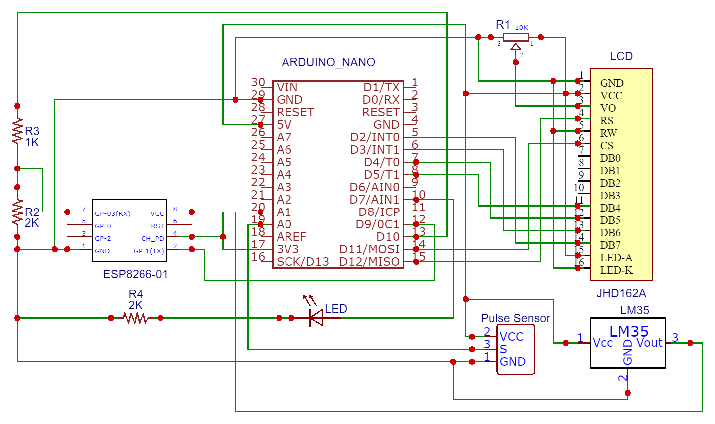
Circuit Diagram & Connections:
For designing IoT Based Patient Health Monitoring System using ESP8266 & Arduino, assemble the circuit as shown in the figure below.
- Connect Pulse Sensor output pin to A0 of Arduino and other two pins to VCC & GND.
- Connect LM35 Temperature Sensor output pin to A1 of Arduino and other two pins to VCC & GND.
- Connect the LED to Digital Pin 7 of Arduino via a 220-ohm resistor.
- Connect Pin 1,3,5,16 of LCD to GND.
- Connect Pin 2,15 of LCD to VCC.
- Connect Pin 4,6,11,12,13,14 of LCD to Digital Pin12,11,5,4,3,2 of Arduino.
- The RX pin of ESP8266 works on 3.3V and it will not communicate with the Arduino when we will connect it directly to the Arduino. So, we will have to make a voltage divider for it which will convert the 5V into 3.3V. This can be done by connecting the 2.2K & 1K resistor. Thus the RX pin of the ESP8266 is connected to pin 10 of Arduino through the resistors.
- Connect the TX pin of the ESP8266 to pin 9 of the Arduino.
Here is another version of the Schematic designed using EasyEDA software. Instead of using Arduino UNO, you can use Arduino Nano for this project.
Setting the ThingSpeak:
ThingSpeak provides a very good tool for IoT based projects. By using the ThingSpeak site, we can monitor our data and control our system over the Internet, using the Channels and web pages provided by ThingSpeak. So first you need to sign up for ThingSpeak. So visit https://thingspeak.com and create an account.
Then create the
API keys. This key is required for programming modifications and setting your data.
Then upload the code to the Arduino UNO by assembling the circuit shown above. Open the serial monitor and it will automatically connect to Wi-Fi and set up everything.
Now click on channels so that you can see the online data streaming, i.e IoT Based Patient Health Monitoring System using ESP8266 & Arduino as shown in the figure here.
Source Code/Program:
The source code for the project IoT Based Patient Health Monitoring System using ESP8266 & Arduino is given below. Simply copy the code and paste it to your Arduino IDE, then compile it and upload it to your Arduino UNO Board.
#include
LiquidCrystal lcd(12, 11, 5, 4, 3, 2);
#include
float pulse = 0;
float temp = 0;
SoftwareSerial ser(9,10);
String apiKey = "OO707TGA1BLUNN12";
// Variables
int pulsePin = A0; // Pulse Sensor purple wire connected to analog pin 0
int blinkPin = 7 ; // pin to blink led at each beat
int fadePin = 13; // pin to do fancy classy fading blink at each beat
int fadeRate = 0; // used to fade LED on with PWM on fadePin
// Volatile Variables, used in the interrupt service routine!
volatile int BPM; // int that holds raw Analog in 0. updated every 2mS
volatile int Signal; // holds the incoming raw data
volatile int IBI = 600; // int that holds the time interval between beats! Must be seeded!
volatile boolean Pulse = false; // "True" when User's live heartbeat is detected. "False" when nota "live beat".
volatile boolean QS = false; // becomes true when Arduoino finds a beat.
// Regards Serial OutPut -- Set This Up to your needs
static boolean serialVisual = true; // Set to 'false' by Default. Re-set to 'true' to see Arduino Serial Monitor ASCII Visual Pulse
volatile int rate[10]; // array to hold last ten IBI values
volatile unsigned long sampleCounter = 0; // used to determine pulse timing
volatile unsigned long lastBeatTime = 0; // used to find IBI
volatile int P = 512; // used to find peak in pulse wave, seeded
volatile int T = 512; // used to find trough in pulse wave, seeded
volatile int thresh = 525; // used to find instant moment of heart beat, seeded
volatile int amp = 100; // used to hold amplitude of pulse waveform, seeded
volatile boolean firstBeat = true; // used to seed rate array so we startup with reasonable BPM
volatile boolean secondBeat = false; // used to seed rate array so we startup with reasonable BPM
void setup()
{
lcd.begin(16, 2);
pinMode(blinkPin,OUTPUT); // pin that will blink to your heartbeat!
pinMode(fadePin,OUTPUT); // pin that will fade to your heartbeat!
Serial.begin(115200); // we agree to talk fast!
interruptSetup(); // sets up to read Pulse Sensor signal every 2mS
// IF YOU ARE POWERING The Pulse Sensor AT VOLTAGE LESS THAN THE BOARD VOLTAGE,
// UN-COMMENT THE NEXT LINE AND APPLY THAT VOLTAGE TO THE A-REF PIN
// analogReference(EXTERNAL);
lcd.clear();
lcd.setCursor(0,0);
lcd.print(" Patient Health");
lcd.setCursor(0,1);
lcd.print(" Monitoring ");
delay(4000);
lcd.clear();
lcd.setCursor(0,0);
lcd.print("Initializing....");
delay(5000);
lcd.clear();
lcd.setCursor(0,0);
lcd.print("Getting Data....");
ser.begin(9600);
ser.println("AT");
delay(1000);
ser.println("AT+GMR");
delay(1000);
ser.println("AT+CWMODE=3");
delay(1000);
ser.println("AT+RST");
delay(5000);
ser.println("AT+CIPMUX=1");
delay(1000);
String cmd="AT+CWJAP=\"Alexahome\",\"98765432\"";
ser.println(cmd);
delay(1000);
ser.println("AT+CIFSR");
delay(1000);
}
// Where the Magic Happens
void loop()
{
serialOutput();
if (QS == true) // A Heartbeat Was Found
{
// BPM and IBI have been Determined
// Quantified Self "QS" true when arduino finds a heartbeat
fadeRate = 255; // Makes the LED Fade Effect Happen, Set 'fadeRate' Variable to 255 to fade LED with pulse
serialOutputWhenBeatHappens(); // A Beat Happened, Output that to serial.
QS = false; // reset the Quantified Self flag for next time
}
ledFadeToBeat(); // Makes the LED Fade Effect Happen
delay(20); // take a break
read_temp();
esp_8266();
}
void ledFadeToBeat()
{
fadeRate -= 15; // set LED fade value
fadeRate = constrain(fadeRate,0,255); // keep LED fade value from going into negative numbers!
analogWrite(fadePin,fadeRate); // fade LED
}
void interruptSetup()
{
// Initializes Timer2 to throw an interrupt every 2mS.
TCCR2A = 0x02; // DISABLE PWM ON DIGITAL PINS 3 AND 11, AND GO INTO CTC MODE
TCCR2B = 0x06; // DON'T FORCE COMPARE, 256 PRESCALER
OCR2A = 0X7C; // SET THE TOP OF THE COUNT TO 124 FOR 500Hz SAMPLE RATE
TIMSK2 = 0x02; // ENABLE INTERRUPT ON MATCH BETWEEN TIMER2 AND OCR2A
sei(); // MAKE SURE GLOBAL INTERRUPTS ARE ENABLED
}
void serialOutput()
{ // Decide How To Output Serial.
if (serialVisual == true)
{
arduinoSerialMonitorVisual('-', Signal); // goes to function that makes Serial Monitor Visualizer
}
else
{
sendDataToSerial('S', Signal); // goes to sendDataToSerial function
}
}
void serialOutputWhenBeatHappens()
{
if (serialVisual == true) // Code to Make the Serial Monitor Visualizer Work
{
Serial.print("*** Heart-Beat Happened *** "); //ASCII Art Madness
Serial.print("BPM: ");
Serial.println(BPM);
}
else
{
sendDataToSerial('B',BPM); // send heart rate with a 'B' prefix
sendDataToSerial('Q',IBI); // send time between beats with a 'Q' prefix
}
}
void arduinoSerialMonitorVisual(char symbol, int data )
{
const int sensorMin = 0; // sensor minimum, discovered through experiment
const int sensorMax = 1024; // sensor maximum, discovered through experiment
int sensorReading = data; // map the sensor range to a range of 12 options:
int range = map(sensorReading, sensorMin, sensorMax, 0, 11);
// do something different depending on the
// range value:
switch (range)
{
case 0:
Serial.println(""); /////ASCII Art Madness
break;
case 1:
Serial.println("---");
break;
case 2:
Serial.println("------");
break;
case 3:
Serial.println("---------");
break;
case 4:
Serial.println("------------");
break;
case 5:
Serial.println("--------------|-");
break;
case 6:
Serial.println("--------------|---");
break;
case 7:
Serial.println("--------------|-------");
break;
case 8:
Serial.println("--------------|----------");
break;
case 9:
Serial.println("--------------|----------------");
break;
case 10:
Serial.println("--------------|-------------------");
break;
case 11:
Serial.println("--------------|-----------------------");
break;
}
}
void sendDataToSerial(char symbol, int data )
{
Serial.print(symbol);
Serial.println(data);
}
ISR(TIMER2_COMPA_vect) //triggered when Timer2 counts to 124
{
cli(); // disable interrupts while we do this
Signal = analogRead(pulsePin); // read the Pulse Sensor
sampleCounter += 2; // keep track of the time in mS with this variable
int N = sampleCounter - lastBeatTime; // monitor the time since the last beat to avoid noise
// find the peak and trough of the pulse wave
if(Signal < thresh && N > (IBI/5)*3) // avoid dichrotic noise by waiting 3/5 of last IBI
{
if (Signal < T) // T is the trough
{
T = Signal; // keep track of lowest point in pulse wave
}
}
if(Signal > thresh && Signal > P)
{ // thresh condition helps avoid noise
P = Signal; // P is the peak
} // keep track of highest point in pulse wave
// NOW IT'S TIME TO LOOK FOR THE HEART BEAT
// signal surges up in value every time there is a pulse
if (N > 250)
{ // avoid high frequency noise
if ( (Signal > thresh) && (Pulse == false) && (N > (IBI/5)*3) )
{
Pulse = true; // set the Pulse flag when we think there is a pulse
digitalWrite(blinkPin,HIGH); // turn on pin 13 LED
IBI = sampleCounter - lastBeatTime; // measure time between beats in mS
lastBeatTime = sampleCounter; // keep track of time for next pulse
if(secondBeat)
{ // if this is the second beat, if secondBeat == TRUE
secondBeat = false; // clear secondBeat flag
for(int i=0; i<=9; i++) // seed the running total to get a realisitic BPM at startup
{
rate[i] = IBI;
}
}
if(firstBeat) // if it's the first time we found a beat, if firstBeat == TRUE
{
firstBeat = false; // clear firstBeat flag
secondBeat = true; // set the second beat flag
sei(); // enable interrupts again
return; // IBI value is unreliable so discard it
}
// keep a running total of the last 10 IBI values
word runningTotal = 0; // clear the runningTotal variable
for(int i=0; i<=8; i++)
{ // shift data in the rate array
rate[i] = rate[i+1]; // and drop the oldest IBI value
runningTotal += rate[i]; // add up the 9 oldest IBI values
}
rate[9] = IBI; // add the latest IBI to the rate array
runningTotal += rate[9]; // add the latest IBI to runningTotal
runningTotal /= 10; // average the last 10 IBI values
BPM = 60000/runningTotal; // how many beats can fit into a minute? that's BPM!
QS = true; // set Quantified Self flag
// QS FLAG IS NOT CLEARED INSIDE THIS ISR
pulse = BPM;
}
}
if (Signal < thresh && Pulse == true)
{ // when the values are going down, the beat is over
digitalWrite(blinkPin,LOW); // turn off pin 13 LED
Pulse = false; // reset the Pulse flag so we can do it again
amp = P - T; // get amplitude of the pulse wave
thresh = amp/2 + T; // set thresh at 50% of the amplitude
P = thresh; // reset these for next time
T = thresh;
}
if (N > 2500)
{ // if 2.5 seconds go by without a beat
thresh = 512; // set thresh default
P = 512; // set P default
T = 512; // set T default
lastBeatTime = sampleCounter; // bring the lastBeatTime up to date
firstBeat = true; // set these to avoid noise
secondBeat = false; // when we get the heartbeat back
}
sei(); // enable interrupts when youre done!
}// end isr
void esp_8266()
{
// TCP connection AT+CIPSTART=4,"TCP","184.106.153.149",80
String cmd = "AT+CIPSTART=4,\"TCP\",\"";
cmd += "184.106.153.149"; // api.thingspeak.com
cmd += "\",80";
ser.println(cmd);
Serial.println(cmd);
if(ser.find("Error"))
{
Serial.println("AT+CIPSTART error");
return;
}
String getStr = "GET /update?api_key=";
getStr += apiKey;
getStr +="&field1=";
getStr +=String(temp);
getStr +="&field2=";
getStr +=String(pulse);
getStr += "\r\n\r\n";
// send data length
cmd = "AT+CIPSEND=4,";
cmd += String(getStr.length());
ser.println(cmd);
Serial.println(cmd);
delay(1000);
ser.print(getStr);
Serial.println(getStr); //thingspeak needs 15 sec delay between updates
delay(3000);
}
void read_temp()
{
int temp_val = analogRead(A1);
float mv = (temp_val/1024.0)*5000;
float cel = mv/10;
temp = (cel*9)/5 + 32;
Serial.print("Temperature:");
Serial.println(temp);
lcd.clear();
lcd.setCursor(0,0);
lcd.print("BPM :");
lcd.setCursor(7,0);
lcd.print(BPM);
lcd.setCursor(0,1);
lcd.print("Temp.:");
lcd.setCursor(7,1);
lcd.print(temp);
lcd.setCursor(13,1);
lcd.print("F");
}
Video Tutorial & Explanation:
Watch this full video for full understanding and setting up things.
https://youtu.be/h_0rKdVboRw


Can help me the date read in lcd but in the thigspeak not found
ReplyDeleteplease sent code clarly
ReplyDelete